Articles:


Measuring and Monitoring Student Learning using an Educational Software
Engineering Environment
E.A.Dodman and J.F.Coxhead
Software Technology Group
Leeds Metropolitan University
The Grange, Beckett Park , Leeds LS6 3QS, U.K.
Table of Contents
Abstract
Introduction
Teaching Philosophy
The Tools
User Interface
Experience of Using the Environment
Summary
Acknowledgements
References
Current Contact Address
ABSTRACT
The craft of the software engineer is complex and difficult. The end
result of the work of a software engineer is a software product. Much work
is being done on measuring both the quality of the final product and the
process by which it is achieved. However the quality obviously depends
crucially on the ability of the persons developing the product. Education
and training is therefore a vital component. Unfortunately quality
measures for the product of an educational system ( the graduate student )
and the process of production (the learning/teaching process) are not
easily defined or measured. The work described in this paper relates to
the education of software engineers and an approach to the measurement of
how successful this is in producing a quality software engineer. It is
hoped that many aspects of the research can be applied to other areas of
education.
This paper describes the results obtained from the system and discusses
their implications with respect to the provision and measurement of the
effectiveness of automated environments for learning. Particular attention
is paid to the interface model used and measures of it's ability to
satisfy the requirements of ease of learning, ease of use and competence
to handle the complete range of student ability and experience.
INTRODUCTION
Commercial software tools are understandably built primarily to meet the
needs of the professional practitioner. The combination of the software
and the hardware on which to run it therefore reflects certain assumptions
about the commercial enterprise in which professionals practice. As most
software tool development is market driven the money making value added
features result in a wide selection of interfaces which poses a problem
for academic teaching and skill transfer.
The teaching enterprise, although having to deal with the same
technologies, differs greatly in its tool requirements and hardware
configurations. The group based requirements of the teaching environment
are often at variance with the more individually based commercial working
practices. The consequence of this is that the purchase of popular
commercial tools for academic use more often than not will not satisfy
perceived academic requirements. Overfunctionality, long learning curves
for different interfaces and lack of integration may create their own
problems. In the worst case courses may have to be re-modelled around
making best use of such costly tools as are available rather than the tool
being configured to teaching needs.
A long-running project at Leeds Metropolitan University has been to devise
an Educational Integrated Project Support Environment for use in the
training of students of Computing. The philosophy underlying it's
development was that of enabling students to be educated in basic design
principles while using tools which would enable easy transferability to
the commercially available tools commonly found in the software
development industry. The environment was to be used throughout the
complete course (degree or otherwise) that the student was studying. A
consequence of this was that the environment and it's incorporated tools
had to present an easily-learned interface to the user that was consistent
throughout the entire period of a student's study. The interface had
therefore to be straightforward to learn and simple to use by students at
the start of their course. It also had to have the capability to handle
the sophisticated commercial standard tools used by final year and
post-graduate students.
TECHNOLOGY
What was clearly needed was a configurable environment in which we could
alter tool functionality and interface at will and with minimum effort.
Meta-CASE has provided us with such a facility [5]. The product we used
to construct the environment, the IPSYS Toolbuilding Kit, is derived from
technology which originated in the early ALVEY and ESPRIT projects.
A significant breakthrough with Meta-CASE is genericity and re-use at a
high level. A good example of this is a graphic design editor which is
usually required with most CASE tools. Usually each instance of such an
editor is built from a lower level using components of some language
library. With Meta-CASE the whole diagram editor can be built to
facilitate re-use by parameterising it to support a number of different
methods.
The power of this type of high level re-use is that generic user
interfaces can be constructed across all tools and the functionality of
the tool can be quickly altered as large parts of the application
interface are also generic. Other features of Meta-CASE include full
control over all the database schemas (objects defined in a database to
represent a particular method), an inherent messaging system and context
related help structures.
TEACHING PHILOSOPHY
A teaching philosophy was defined to incrementally teach students in
stages over their course period. The use of meta-CASE technology enables
tools to be tailored to the current level of student ability and to be
modified to meet tutor requirements whilst still retaining full
compatibility and interoperability. The environment provides tools to
facilitate the teaching of individual design techniques but also
incorporates the use of full industry-standard methods and techniques
(e.g. SSADM, IE, HOOD) as required in the later stages of a course. The
flexibility of the system enables us to address the problem that
academically students need to understand basic principles whereas to get a
job they often need facility in currently popular methods. The actual
design philosophy and architecture of the system is described in the
papers [ 1,2,3,4].
Initially it was thought that three levels of tool would be required
starting with basic diagramming tools based on a single technique and
ending with the students being subjected to full toolsets based on a
particular method. The basic diagramming tools are referred to as tool
fragments and the highest level tools are referred to as fully integrated
toolsets. An intermediate set of tools known as intermediate tools were
developed; these were again based on a single technique but had an
underlying data dictionary and supported a number of automated features.
However, from trials it has been found that there is no real need for the
intermediate tools as the strength of the generic interfaces allows
students to transfer their skills directly from the tool fragments to the
fully integrated tools.
THE TOOLS
A major problem with teaching software engineering is that practical
experience is more often than not gained from using tools/toolsets
developed for the seasoned practitioner and these are overwhelming for
inexperienced students. However, the strategy for teaching software
engineering is no different from that for most vocational subjects in that
the overall view of the subject area is broken down into logical and
manageable modules. The modules will usually represent a particular
technique which may be taught in isolation (although it may depend on
previously covered material). As most techniques are complex in their full
extent it is usual practice to start with the smallest possible subset and
add to this over time.
The tool fragments are designed to mirror such a strategy. What has been
developed is a selection of tools supporting different techniques and
notations. Each tool interface is identical the only difference being the
contents of the menus, the shapes of the graphic objects that can be put
on the screen (notations for different techniques) and the rules governing
the relationship between the graphic objects (the technique itself).
The functionality and syntax of the tool can be reduced to that of a
required starting subset as requested by the tutor. For example the tutor
may not want to start with a full set of technique icons or to have the
rules that govern the syntax fully automated. The missing features can
then be replaced over time in step with course development again at the
request of the tutor.
There is a second motive to using the tool fragments and that is
familiarisation with the underlying operating system. To incorporate
fully the learning of the operating system most file management tasks are
deliberately left for the student to carry out within the operating system
file manager (copy, rename, new version etc).
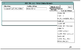
Figure 1 shows a screen dump of the tool fragment menu demonstrating the
range of tool fragments available, all of which may be selected from a
master window.
USER INTERFACE
The environment is designed to be used by students at all levels of
training. To ensure this a consistent house-style was adopted for the
environment interface. The meta-CASE technology used in developing the
environment then allowed the construction of a generic graphical user
interface which could be tailored to the needs of particular student
groups. As the students using the environment were all computing students
a control panel metaphor was selected as being the most appropriate for
the interface rather than the more common desk top model. This control
panel metaphor is the standard model provided by the IPSYS toolset.
Although different models of interface can be swiftly generated we decided
to base our model on this IPSYS house style believing that the control
panel metaphor was more appropriate and easier to use by software
engineering students than the more usual desk-top metaphor found in most
windowing systems.
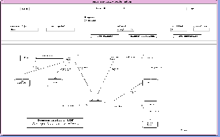
Figure 2 shows a screen dump of a tool fragment in use. The bottom part
of the screen is a graphical window holding the design diagram currently
being worked on. The upper part of the screen represents the control panel
with drop down menus, signs and buttons and is is generic to all tool
fragments. The blank line between the two parts of the screen is a message
window used to report any system messages back to the user.
The philosophy behind this approach is that of minimum surprise with
standard naming, placing and actions of buttons, switches and menus across
all tools. In any particular menu users are always offered only valid
selections for that menu. As an example of this we can take a Data Flow
Diagram technique where we can add a process to our diagram. The process
will have attributes that could be added to it such as name and
identification. If these attributes are single instance attributes once
they have been added they will disappear from the menu selection.
As students progress through their course they move through the full
range of tools ending up using one or more of the fully integrated
toolsets (the current selection is SSADM v4, HOOD, Information Engineering
and a number of Object Oriented toolsets) but always seeing a common
interface with only those differences ( for example the syntax of the
method ) necessary to support the particular toolset being used.

Figure 3 is a screen dump representing the use of a full commercial SSADM
Version 4 tool ( constructed using IPSYS Tool Builder ). The tool's
Structure Editor ( left hand side of the screen ) and Diagram Editor (
right hand side ) are both displayed together.
When students are faced with large complex toolsets one of the common
problems is that they may get lost down several levels of menus. Within
the IPSYS Meta-CASE environment this is not a problem as everything is
hypertext based. As well as having a generic design editor there is also
a generic structure editor. The main purpose of a generic structure
editor is to be able to represent a structured textual view as opposed to
a diagrammatic view of the system. The structured text editor has a
control panel to handle such things as printing, saving, history and
context. However, navigation and editing are done through the actual
textual objects. A menu can be attached to a single letter, a word, a
line or a block. Navigation is handled by pointing at one of these areas
and selecting the next action from the popped up menu. A path is always
visible so users know where they are and any part of the path is
selectable to return to any level.
TOOL BUILDING
With this type of high level re-use tools supporting similar techniques or
methods can be very rapidly prototyped. For example once you have created
one data flow diagramming tool then a whole range of similar tools with
different notations can be built very quickly. There are several levels
of development, the highest being the one just described, the next level
down would be to develop a completely new technique or method. This would
take a little longer as it would involve the definition of a completely
new database schema. However, the generic design editor and structure
editor is still used to present and manipulate the technique/method which
still makes the development process considerably faster than conventional
developments of this type. If you find that there is not a pre-defined
built-in function in the existing libraries that you require to support
your new method then you have the capability to drop to the language level
and create one.
The latest innovation with the IPSYS Meta-CASE product is a tool building
tool called Toolbuilder. The toolbuilder tool looks and feels just like
the tools it builds. With toolbuilder you can define a method using an
entity modelling technique; the entity model is automatically converted to
its equivalent text structure which is linked to a pre-defined set of
templates. Once the templates have been populated the whole model is
compiled and the tool is made by running a generic make file.
EXPERIENCE OF USING THE ENVIRONMENT
The system has been installed and operational at the level described for
two years and is accepted enthusiastically by students. Students find the
interface easy to learn and have no difficulty in transferring between
different tools. It is this that has led us to decide that the
intermediate tool level we originally envisaged was not necessary. The
environment has proved popular in that students not only use it as
required in various parts of their courses but drop in and use it on an
open access basis for preparing work in other parts of their course. This
practical demonstration of popularity is confirmed by student response to
follow-up questionnaires. The standard of coursework submitted has
improved both in terms of presentation standard and better design of
systems. The latter is felt to be due to the fact that the ease of use of
the system encourages students to spend more time on coursework.
Having been successful in the implementation of the system it was felt to
be an appropriate time to move on to the more demanding consideration of
measuring how the environment affected, and could be used to monitor, the
quality of the work students produce and the quality of their learning
experience. This will also incorporate measurement of the tools fitness
for purpose. In order to be fully in control of the educational process it
is necessary to consider the quality of the student the effectiveness of
the teaching approach taken the effectiveness of the environment in the
support of course delivery and to provide measurable criteria for each of
them. These tasks are in decreasing order of difficulty but all are
formidable. In order to obtain this we have started to incorporate
measuring and monitoring tools into the environment. This is made readily
possible because the IPSYS environment has a built in messaging system
incorporated in all its tool instances. All messages generated while in
the system are routed to a session log and this log has been exploited by
us to monitor system usage. There are 11 types of message covering not
only errors but such things as warnings and metrics thus enabling us to
obtain a comprehensive view of a student's use of the system.
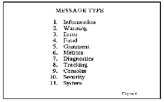
Figure 4 is a full list of message types produced by the system which may
be monitored via a session log.
Measurement tools are being incorporated into the system initially to
quantitatively monitor the systems performance and usage. These tools will
be used to evaluate the environment's fitness for purpose and enable the
building up of profiles of student usage of the system and progress
through the course. This will enable detection of aspects of the system
which are not satisfying the requirements but, more importantly, will
enable the early detection of students who are experiencing difficulties.
When profiles of normal student usage are built up it should be possible
to provide automatic triggers in the system which will initiate aid to the
student. This may be on-line help, supportive tuition from the tutor or,
in future, might incorporate on-line corrective training.
The aim of the monitoring is initially to test the effectiveness of the
environment and the toolsets in their role as a teaching environment. The
next aim is to monitor how well students are assimilating the methods and
techniques they are taught. This will initially enable the early detection
of students who are experiencing difficulties and allow early remedial
help to be given. It will also provide support for tutors in terms of
assessment and appraisal. The long term aim is to incorporate interactive
teaching and remedial assistance for the students.
Monitoring and measuring can assist in many areas -
1. Monitoring individual tools for fitness of purpose
2. Monitoring students and providing class and individual profiles. These
will flag gaps in understanding in both individuals and the group.
3. Assisting tutors in recognising absenteeism, plagiarism and areas of
weakness requiring corrective or remedial teaching.
4. Assisting course leaders and course teams in identifying areas of
weakness in satisfying the learning objectives of courses
5. Assisting technical staff by providing statistics on system usage, peak
loading periods and indicating system weaknesses and shortfalls.
This monitoring phase of the project has reached the stage where the
programs for analysing the messages have been incorporated into the
system. It is currently being used to analyse data for complete classes of
students to enable average student profiles to be built up. This is
necessary to enable the detection of students with particular problems.
Some of the analysis available to the system is demonstrated in the
figures below.
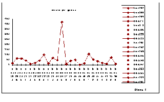
Figure 5 shows a profile of errors made by a single class of students
during a laboratory session. The graph highlights one student as having
made many more errors than the average and flags the need for further
investigation. Such crude analysis does not indicate the student was worse
than the others as there is no indication of the type and level of work
each student is pursuing but does indicate that the work of this student
needs further investigation.
Analysis of each error type and frequency over the whole student cohort
is required in order to highlight common misunderstanding or teaching
omission.
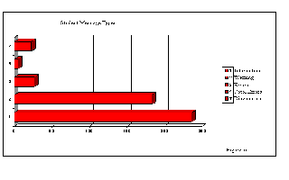
Figure 6 gives a profile of the messages received by a single student
during a single session.
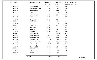
Figure 7 shows a class report for a set piece of work. This is of use to
tutors as a measure of how much system time students have required to do a
particular piece of work and to technical staff as a mesure of system
loading.

Figure 8 displays a class profile of all messages generated throughout a
two hour laboratory session broken down into 10 minute intervals.
SUMMARY
The environment we have described is complex and incorporates state of the
art technology and toolsets. However students at all levels find it easy
to use largely because of the straightforward and simple user interface
level used. Tutors find the environment helpful in that the tools and
techniques taught can be tailored to suit pedagogic needs. Monitoring
facilities are now incorporated into the environment which will enable
measurement of not only the quality of the system but also the quality of
the work students are producing. The ultimate goal is to merge this with
on-line interactive teaching for the students.
The system as described has been designed especially for students of
software engineering. It is felt however that the monitoring and appraisal
is relevant to students over a wide range of subjects and we hope to
utilise the experience obtained here in other areas of teaching. It also
has potential application in the commercial sector as a means for
facilitating Quality Audit [7].
ACKNOWLEDGEMENTS
The authors would like to thank Mark Dixon for his help in preparing the
paper and in particular Yvonne Bulmer for all the work and commitment she
put in during her period of work placement.
REFERENCES
1. Coxhead, Dodman and Harvey
CASE requirements for teaching software engineering.
Proc. 4th UK ISTIP conference: AIT 1991, pps 65-69.
2. Coxhead, Harvey and Dodman
CASE and the education of software engineers.
Proc. SEHE conference: Southampton Institute 1991,pps 174-177.
3. Coxhead, Harvey and Dodman
An integrated environment and teaching philosophy for the education
of software engineers.
Proc. 5th UK ISTIP conference: AIT 1992, pps 89-93.
4. Coxhead, Dodman and Harvey
CASE technology: improving quality in the education of software
engineers.
Software Quality Management, Eds. Ross, Brebhia, Staples & Stapleton:
Computational Mechanics Publications, Elsevier 1993, pps 317-330.
5. Alderson.A.
Meta_CASE Technology
IPSYS Software plc 1992.
6. Alderson.A.
Beyond Today's CASE Technology Toward Meta-CASE
IPSYS Software plc 1993.
7. Coxhead, Dixon and Dodman
Meta-CASE and Audit: Automated Generic Quality Assessment
Proc: 1st International Congress on META-CASE, University of
Sunderland, 1995.
CURRENT CONTACT ADDRESS
Email address


